◎ 全隔离单相桥式全控整流模块 (DQZ)
FULL ISOLATION SINGLE PHASE FULLY- CONTROLLED BRIDGE RECTIFIER MODULE (DQZ)
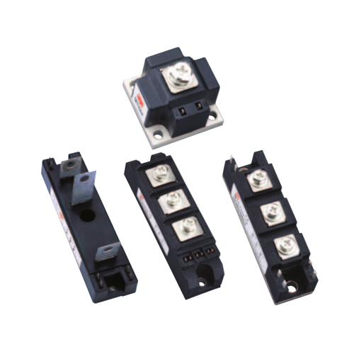
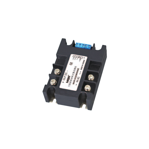
◆ 全隔离单相桥式全控整流模块 ( 以下简称单相整流模块 DQZ) 内部集四只单向可控硅组成的全控桥 , 移相电路和触发电路于一体 , 在外部提供交流同步电压(18VAC) 下 , 便可以自动控制或外接电位器手动控制 ,
达到改变四只单向可控硅的导通角即可方便地实现单相交流电直接转向幅值无级可调地脉动直流电压 .
◆ 单 相 整 流 模 块 DQZ 根 据 单 相 交 流 电 网 电 压分 380V( 可 应 用 180~450VAC), 220V( 可 应 用120~250VAC), 110V( 可应用 50~120VAC), 36V( 可应用20~50VAC) 四大系列; 根据信号的不同分E, F, G,H 等四类
◆ The full isolation single phase fully-controlled bridge rectifier module (hereinafter referred to as the single phase rectifier module DQZ) integrates the fully-controlled bridge rectifier (consisting of four SCR thyristors), the phase-shift circuit and the trigger circuit. Under the AC synchronous voltage (18VAC) provided by external device, the conduction angle of the four SCR thyristors can be changed by the automatic control method or manual control method (i.e. the external potentiometer), which means the single phase AC voltage can be easily converted into the pulsed DC voltage with the continuously adjustable amplitude.
◆ According to the voltage of the single phase AC power grid, the single phase rectifier module DQZ can be divided into four types: 380V type (applicable to 180~450VAC), 220V type (applicable to 120~250VAC), 110V type (applicable to 50~120VAC), and 36V type (can be applied to 20~50VAC). According to different control signals, the single phase rectifier module DQZ can be divided into four types: E, F, G, and H types.
◆ 为方便说明,下面以 0-5V 控制信号为标准作介绍
◆ For convenience of explanation, the following introduces with the 0~5V control signal as a standard

① ② 为 交 流 电 源 进 线 端, 电 压 等 级 分 380VAC、220VAC、110VAC 和 36VAC。
③④为直流输出正负端,负载电压。
⑤⑥为同步电压输入端,允许输入与①②交流电源同步的幅值为 18±5VAC 的电压,⑤与②为同步端。
⑦ ⑧ ⑨ 分 别 为 +5V CON 和 COM, 其 中 +5V 为 模块内部产生,只供电位器手动控制用,CON 为控制端,COM 为内部地端。其中的①②③④的强电部分与
⑤⑥⑦⑧⑨的弱电部分为全隔离。
① and ② ports are the AC power supply input terminals of the module, and the voltage grade can be divided into 380VAC, 220VAC, 110VAC and 36VAC.
③ and ④ are DC output positive and negative terminals of the load voltage respectively
⑤ and ⑥ ports are the synchronous voltage input terminals, allowing the input voltage with amplitudes of 18 ± 5 VAC (synchronized with AC power supply of ① and
② ports). ⑤ and ② ports are synchronous terminals.
⑦, ⑧ and ⑨ ports are +5V port, CON port and COM port respectively. COM port is the internal common ground terminal, CON port is the control terminal, and the +5V port
is the power supply generated inside the module only for the manual control of potentiometer. The strong current part (①, ②, ③, and ④ ports) and the weak current part
(⑤, ⑥, ⑦, ⑧, and ⑨ ports) are fully isolated.

注:以上电流等级为模块输出电流最大有效值。
Note: The current grade in this table is the maximum rms current of the module.
◎ 有关技术指标及应注意的问题
Related technical specifications and precautions
1、当输出端并联电解电容滤波时 , 由于电容两端电压不能突变 , 这种高压 , 大容性场合很容易造成模块过流而损 坏 , 因此模块上电前必须保证控制端 CON 电压在 0V,上电后 CON 须从 0V 逐渐增大 , 以保证电容冲击电流最小。
2、 CON 对 COM 必须为正,如积极相反则输出端失控(全开或全闭)。当控制端 CON 从 0-5V 改变时,负载上的电压从 0 伏到最大值可调(对阻性负载而言)。其中 CON 在 0-0.8V 左右时为全关闭区域,可靠关断模块的输出;CON 在 0.8V-4.6V 左右为可调区域,即随着控制电压的增大,导通角∝从 180°到 0°线性最小,负载上的电压从 0 伏增大到最大值;CON 在4.6V-5V左右时为全开通区域,负载上的电压为最大值。
3、CON 对 COM 的输入阻抗分 E、F 和 H 型均为大于等于 30K 欧;G 型为 250 欧。+5V 电压信号只提供给手控电位器用,不作它用,所选用的电位器阻值在2-10KΩ 间。注:4-20mA 的 G 型不能用电位器手动调节,此时 +5V 端也没有用处。
4、当②⑤端不同步时,整个模块无输出,这里只要把⑤、⑥端两根线对调一下即可。同步变压器功率 2W 即可,我公司有 220V、18V(2W);380V/18V(2W)配套供应。
5、整个模块的发热量按负载实际电流安倍数乘每安倍3.0 瓦计算,散热器可选用 MG-L、MG-H 系列。
6、弱电部分、强电部分、模块底板相互间绝缘电压均大于 2000VAC。
7、单相整流模块只能使用在 50Hz 的电网上,其中220V 系 列 使 和 在 120-250VAC 电 网 上,110V 和36V 系列分别使用在 50-120VAC 和 20-50VAC 电网上,380V 系列使用在 180-450VAC 电网上,但⑤⑥两端的同步电压必须在 18V±5VAC 范围内。
8、有关电流等级的选取及保护等有关使用注意事项请参考单相交流固态继电器说明。
1、When the output terminal of the module is connected in parallel with an electrolytic capacitor to filter, the voltage across the capacitor cannot be abruptly changed, so in this high-voltage and large-capacity case, the module will be damaged due to overcurrent. Therefore, before the module is powered on, it must ensure that the voltage on the control terminal CON is 0V, and after power- on, the voltage on the control terminal CON must be gradually increased from 0V to ensure the minimum surge current of the capacitor.
2、CON must be positive relative to COM, and if the polarity is opposite, the output terminal will be out of control (fully open or fully closed). When the control terminal CON changes from 0V to 5V, the voltage on the AC load can be adjusted from 0V to the maximum value (for resistive loads). When the control voltage on CON is around 0V~0.8V (Fully- closed Region), the control signal can reliably shut down the output of the module. When the control voltage on CON is around 0.8V~4.6V (Adjustable Region), the conduction angle α decreases linearly from 180° to 0° as the control voltage increases, and the voltage on the AC load increases from 0V to the maximum value. When the control voltage on CON is around 4.6V~5V (Full-open Region), the voltage on the AC load is the maximum value (close to the power grid voltage).
3、The input impedance between CON and COM is divided into E