◎ 固态继电器三相移相触发器模块(SSR-3JK)
SOLID STATE RELAY THREE PHASE PHASE-SHIFT TRIGGER MODULE (SSR-3JK)
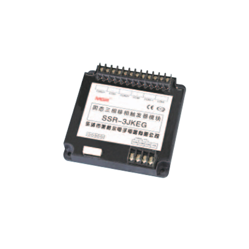
◆ 固态继电器三相移相触发器模块 ( 以下简称 SSR-3JK) 内部集三相电相位检测 , 移相电路 , 控制电路和三路单相随机型固态继电器触发电路于一体 , 在由我公司提供的三相同步变压器模块 ( 型号为 TB-3) 的支持下 ,不需外部任何电路或工作电源 , 便可以自动控制或电位器手动控制 , 产生三路可改变导通角度的脉冲信号再去分别控制三路单相随机型固态继电器 , 即可实现三相负载电压从 0V 到电网全电压的无级可调。
◆ 按控制信号的不同,SSR-3JK 分 E、F、G 和 H 型等四类,以下为规格型号表。
◆ The solid state relay three phase phase-shift trigger module (hereinafter referred to SSR- 3JK) integrates the three phase phase-detection circuit, the phase-shift circuit, the control circuit
and the trigger circuit of three single phase random conduction type solid state relays. With the support of the three phase synchronous transformer module (TB-3) provided by our company and no requirement for the external circuit or power supply, by the automatic control method or manual control method (i.e. the external potentiometer), three pulse signals which can change the conduction angle will be generated to control three single phase random conduction type solid state relays respectively, which means the voltage amplitude of the three phase load can be continuously adjusted from 0V to the maximum voltage of the power grid.
◆ According to different control signals, SSR-3JK can be divided into four types: E, F, G, and H types. The following is the specification model table.


◎ 有关技术指标及应注意的问题 Related technical specifications and precautions
1. 整个电路可应用于 380VAC (300~420VAC), 50Hz电网上 , 主电路中三相进线 (R, S, T) 无相序要求 , 但进线和固态继电器 , TB-3, SSR-3JK 输出端间 ( 如 T 对应的 SSR1 和 CON1) 必须严格一一对应 , 否则系统不能正常工作。
2.CON 对 COM 必须为正 , 如极性相反则输出端失控( 全开或全闭 ). 当控制端 CON 从 0~5V 改变时 , 交流负载上的电压从0V到最大值可调(对阻性负载而言).其中 CON 在 0~0.8V 左右时为全关闭区域 , 能可靠关断模块的输出 ; CON 在 0.8V~4.6V 左右为可调区域 , 即随着控制电压的增大 , 导通角 α 从 180°到 0°线性减小 , 交流负载上的电压从 0V 增大到最大值 ; CON 在4.6V~5V 左右时为全开通区域 , 交流负载上的电压为最大值 ( 接近电网电压 )。
3. CON 对 COM 的输入阻抗分 E, F 和 H 型均为大于等于 30KΩ; G 型为 250Ω. +5V 电压信号只提供给手控电位器用 , 不做他用 , 所选用的电位器阻值在 2~10KΩ间 , 注 : 4~20mA 的 G 型不能用电位器手动调节 , 此时+5V 端也没有用处。
4.SSR-3JK的四个COM在模块内部均相连, 为弱电”地”, ( 与同步变压器的中性线的”地 N 为全隔离”) 在自动控制方式时与外电路控制的直流”地”相连。
5. 三相负载的三相功率应均衡 . 负载为 Y 形接法时 , Y的中心点接与不接中性线均可 , 但接中性线时高次谐波对电网干扰要比不接中性线时大 . 同步变压器 TB-3 上的 N 线必须可靠接地 ( 中性线 )。6.SSR-3JK 和 TB-3 本身发热很小 , 不需要安装在散热器上。
7. 三相交流异步电机的调速应采用变频器 , 只有风机类 ,水泵类电机在要求不高的场合可采用三相调压模块 . 三相电机软启动应采用电压 , 电流闭环控制。
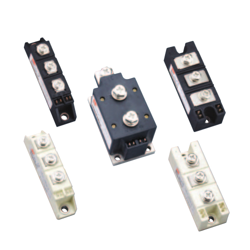
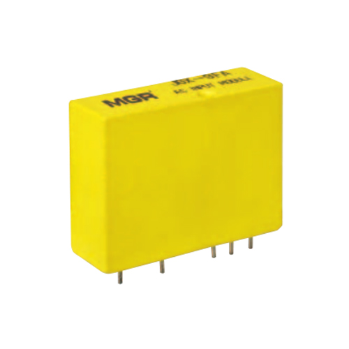
8. 由于 SSR-3JK 一方面通过同步变压器 TB-3 与电网隔离 , 另一方面通过三路固态继电器与电网隔离 , 因此SSR-3JK 模块在弱电工作下极为可靠 , 并且即使三相负载发生短路而烧毁固态继电器后 , SSR-3JK 也不会损坏 . 由于这一原因 , 由 SSR-3JK 组成的三相调压系统比较合理 : 一方面比我公司生产的三相移相触发器模块调压系统 (SX-JKA 加六个单向可控硅 ) 连接更为简便可靠 , 即使产生故障造成的损失也比较小 (SSR-3JK系统短路时只损失一只或两只 SSR, 而 SX-JKA 系统不但损失可控硅 , 而且还可能造成 SX-JKA 模块的损坏 ); 另一方面也比我们公司或其他公司生产的三相调压模块 ( 移相触发电路与可控硅为一体 ) 更为可靠 , 因为三相调压模块集六个单向可控硅于一体 , 由于体积小发热量大 , 散热不良而造成不可靠 , 在负载过流时所造成的损失则更不能相提并论。SSR-3JK( 带 TB-3) 与我公司生产的随机型固态继电器相匹配 , 用户可通过购买 SSR-3JK, TB-3, 三只随机型 SSR 和一块散热器来搭建 SSR-3JK 系统 ( 其中三只长条状固态继电器可安装在带风扇的 Y 系列模块专用散热器上 ; 三只长方状固态继电器可安装在 MG-Y 的散热器上作为一个功率单元 )。
1. The entire circuit can be applied to 380VAC (300~420VAC), 50Hz power grid. The three phase input cables (R, S, T) in the main circuit has no phase sequence requirements, but the input cables must be strict one-to-one correspondence with the output terminals of the solid state relay, TB-3, and SSR-3JK (such as T corresponding to SSR1 and CON1), otherwise the system will not work normally.
2.CON must be positive relative to COM, and if the polarity is opposite, the output terminal will be out of control (fully open or fully closed). When the control terminal CON changes from 0V to 5V, the voltage on the AC load can be adjusted from 0V to the maximum value (for resistive loads). When the control voltage on CON is around 0V~0.8V (Fully- closed Region), the control signal can reliably shut down the output of the module. When the control voltage on CON is around 0.8V~4.6V (Adjustable Region), the conduction angle α decreases linearly from 180° to 0° as the control voltage increases, and the voltage on the AC load increases from 0V to the maximum value. When the control voltage on CON is around 4.6V~5V (Full-open Region), the voltage on the AC load is the maximum value (close to the power grid voltage).
3. The input impedance between CON and COM is divided into E, F and H type (the impedance of these three types are greater than or equal to 30KΩ), and G type (the impedance is 250Ω). The +5V voltage signal is only provided for the manual potentiometer (the selected resistance is between 2~10KΩ), not for other uses. Note: The G type (4~20mA as control signal) cannot be manually adjusted by the potentiometer, so the +5V port is useless for the G type.
4. The four COM ports of the SSR-3JK are connected together inside the module to form the weak current “earth ground” (fully isolated with the neutral line “N line” of the synchronous transformer), which will be connected to the DC “earth ground” controlled by the external circuit when choose the automatic control mode.
5. The power of the three phase load should be balanced. When the load uses the Y-connection method, the center point Y can be connected or not connected to the neutral line. However, the high- order harmonic interference to the power grid when connected to the neutral line is larger than that when not connected to the neutral line. The N line on the synchronous transformer TB-3 must be reliably connected to the earth ground (the neutral line).
6. SSR-3JK and TB-3 generate very little heat and do not need to be mounted on a heat sink.
7. The speed control of the three phase AC asynchronous motor should be adjusted by the frequency converter, while the three phase voltage regulation module can only be applied to fan motors and pump motors where the requirements are not high. For the soft start of the three phase motors, the voltage/current closed-loop control system should be used.
8. Since the SSR-3JK is isolated from the power grid by the synchronous transformer TB-3 on the one hand and isolated from the power grid by three solid state relays on the other hand, the SSR-3JK module is extremely reliable under weak current operation, and will not be damaged even if the three phase load is burned due to short-circuit. For this reason, it is reasonable to choose the three phase voltage regulation system consisting of SSR-3JK (here refers to SSR-3JK system):
Firstly, compared with the three phase phase-shift module voltage-regulation system (here refers to SX-JKA system consisting of SX-JKA an