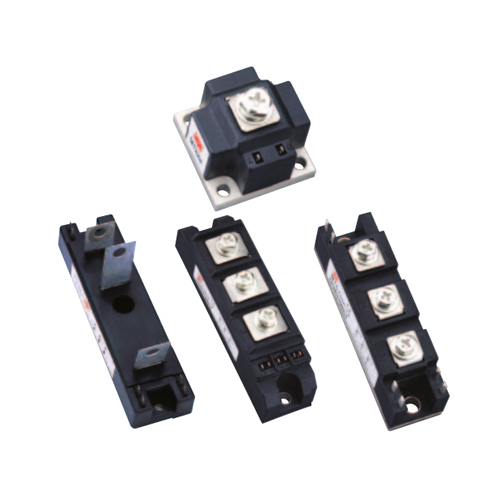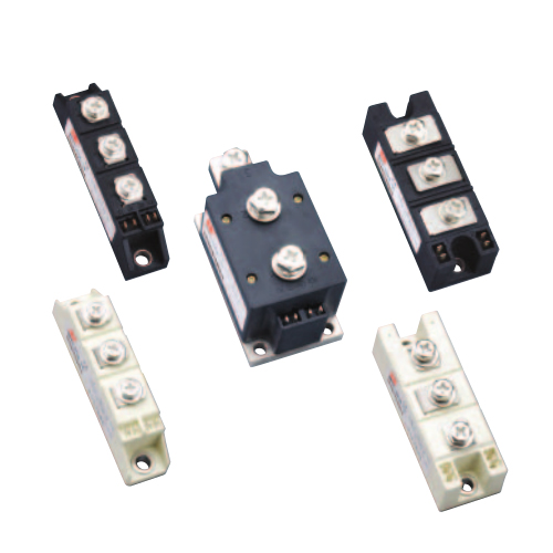
◎ 随机型固态继电器移相触发器模块(SSR-JKWK)
RANDOM CONDUCTION SOLID STATE RELAY PHASE-SHIFT TRIGGER MODULE (SSR-JKWK)
◆ 随机型单相交流固态继电器具有直流控制端施加信号 , 交流输出端便立即导通的性能 , 因此当控制信号为交流电网同步的可移相的脉冲信号时 , 负载端便可以实现从 180°到 0°的范围内电压的平稳调节 . 随机型SSR 的移相触发器模块 ( 以下简称移相触发器 ) 正是为了方便地应用随机型 SSR 来调节交流负载电压而专门设计的 . 移相触发器的功能是根据控制电压的大小 , 输出端产生与电网电压同步的双倍电网频率的从 180°到0°范围内移相的宽脉冲 , 用以驱动随机型 SSR, 从而达到移相调压的目的。
◆ The random conduction type single phase AC solid state relay has such a function that once a signal applied the DC control terminal, the AC output terminal will be turned on immediately. Therefore, if the control signal is a phase-shiftable pulse signal synchronized by the AC power grid, the voltage phase on the load terminal can be adjusted smoothly from 180 ° to 0 ° . The phase-shift trigger module of the random conduction type SSR (hereinafter referred to as the phase-shift trigger) is specially designed for the random conduction type SSR to conveniently adjust the AC load voltage. The function of the phase-shift trigger is to generate a wide pulse (with the synchronization with the power grid voltage, and the frequency twice of the power grid frequency, and the phase can be shifted from 180 ° to 0 ° ) on the output terminal according to the magnitude of the control voltage, to drive the random conduction type SSR to achieve the purpose of phase-shift and voltage-regulation.
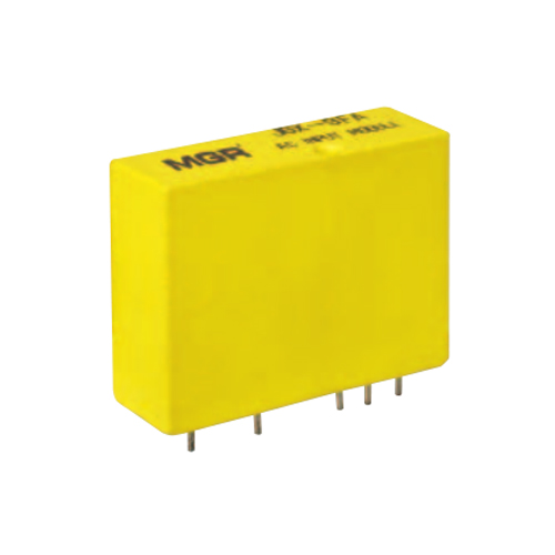
◎ 单相移相触发器模块
SINGLE PHASE PHASE-SHIFT TRIGGER MODULE
◆ 移相触发器是为方便地调节单相交流电压而研制的 . 这个系列有共同的部分 : 在同步电压作用下 ( 此同步电压还作为模块的工作电源 ), 经同步相位检测 , 移相 , 触发 ,便可以自动控制或电位器手动控制 , 产生 180° ~0°可移相的触发信号 , 去触发相应的器件以达到移相调压的目的。
◆ The phase-shift trigger series is developed to conveniently adjust the single phase AC voltage and has the common role: Under the action of the synchronous voltage (which also acts as the operation power of the module), through the synchronous phase-detection circuit, the phase- shift circuit, and the trigger circuit, a phase- shiftable trigger signal (whose phase can be shifted from 180 ° to 0 ° ) will be generated by the automatic control method or manual control method (i.e. the external potentiometer) to trigger the corresponding components to achieve the purpose of phase-shift and voltage-regulation.
◆ 以下规格(型号表)
◆ The following is the specification model table

◆ 为方便说明,下面以 0-5V 控制信号为标准作介绍,
(型号简称 SSR-JKWK)
◆插针式 SSR-JKZK
◆ For convenience of explanation, the following introduces with the 0~5V control signal as a standard
(SSR-JKWK).
◆ Plug-in mounting type (SSR-JKZK)
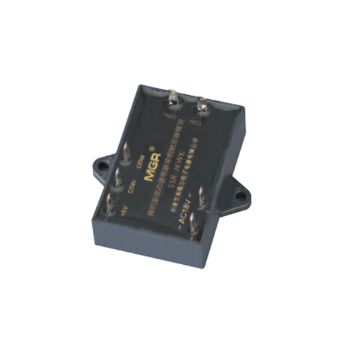
◎ 随机型 SSR 移相触发器的引脚功能
The ports function of the random conduction type SSR phase-shift trigger module
① ②脚同步变压器的副边绕组 18VAC 供给移相触发器电源和同步基准 ;
③脚为内部地 ;
④脚为输出端;
④脚为输出端 ;
⑤脚为内部地 , 当移相触发器由外电路自动控制时 , ⑤脚与外电路的地相连 ;
⑥脚为控制端,当⑥脚输入有 0.5V 电压信号时,④脚输出端便产生 180° -0°的可移相的宽脉冲(对阻性负载而言);
⑦脚为模块内部产生的 +5V 电压端,当⑦⑥⑤脚外接电位器手动控制时,⑦脚提供电源,当外电路提供控制信号时,⑦脚悬空。
The ① and ② ports are connected to the 18VAC secondary winding of the synchronous transformer to offer the power supply and the synchronous reference for the phase-shift trigger;
The ③ port is the internal common ground terminal The foot is the output end;
The ④ port is the output terminal;
The ⑤ port is the internal common ground terminal. If the phase-shift trigger is controlled by the external automatic control circuit, the ⑤ port will be connected to the ground of the external control circuit;
The ⑥ port is the control terminal. When there is a 0.5V voltage signal inputted to the ⑥ port, a wide pulse (whose phase can be shifted from 180 ° to 0° ) will be produced on the output terminal ④ port (for resistive loads);
The ⑦ port is the +5V voltage terminal generated inside the module. If the ⑤ , ⑥ , ⑦ ports are connected to the external potentiometer to apply the manual control method, the ⑦ port acts as the power supply for it; if the control signal is provided by external control circuit to apply the automatic control method, the ⑦ port should be left floating.

◎ 随机型SSR移相触发器模块应用电路图
The application circuit diagram of the random conduction type SSR phase- shift trigger module

◎ 控制电压 U CON 与固态继电器输出导通角 α 关系曲线 ( 阻性负载 ) 及波形图
The relationship and waveform of the control voltage U CON and the conduction angle α of the thyristor (when resistive load)

◎ 有关技术指标及应注意的问题
Related technical specifications and precautions
1. CON 对 COM 必须为正 , 如极性相反则输出端失控( 全开或全闭 ). 当控制端 CON 从 0~5V 改变时 , 交流负载上的电压从 0V 到最大值可调 ( 对阻性负载而言 ). 其中 CON 在 0~0.8V 左右时为全关闭区域 , 能可靠关断模块的输出 ; CON 在 0.8V~4.6V 左右为可调区域 , 即随着控制电压的增大 , 导通角 α 从 180°到 0°线性减小 , 交流负载上的电压从 0V 增大到最大值 ; CON 在 4.6V~5V 左右时为全开通区域 , 交流负载上的电压为最大值 ( 接近电网电压 )。
2. CON 对 COM 的输入阻抗分 E, F 和 H 型均为大于等于 30KΩ; G 型为 250Ω。