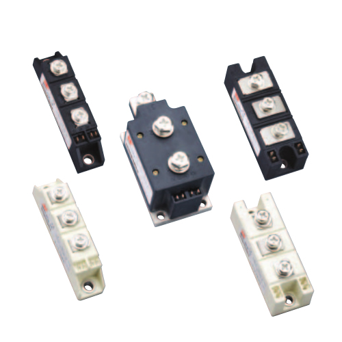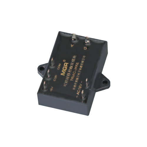
◎ 可控硅移相触发器模块 (SCR-JKK,TRIAC-JKK)
THYRISTOR PHASE-SHIFT TRIGGER MODULE (SCR-JKK, TRIAC-JKK)
◆ 可控硅移相触发器模块分单向可控硅移相触发器模块(SCR-JKK) 和双向可控硅移相触发器模块 (TRIAC-JKK)。
◆ 可控硅移相触发器模块的原理是 : 以电网相位为同步 , 当改变控制电压的大小 , 内部便产生相对电网电压180° ~0°的触发脉冲 , 通过光电隔离 , 输出端 (A, G)便触发相应的可控硅导通 , 从而达到移相调压的目的。
◆ 移相触发器的控制部分由于与输出触发端光电隔离 ,因而可以用手动或者自动两种控制方式 . 在应用中只需提供 18VAC 的电网同步电压 , 电极以插片连接 , 使用极为方便。
◆ SCR-JKK 和 TRIAC-JKK 按控制信号不同 , 分为以下规格 ( 型号表 ):
◆ The thyristor phase-shift trigger module can be divided into the SCR thyristor phase-shift trigger module (SCR-JKK) and the TRIAC thyristor phase-shift trigger module (TRIAC-JKK).
◆ The principle of the thyristor phase-shift trigger module is: The phase of the power grid will be taking as the synchronization reference, and by change the magnitude of the control voltage, a phase-shiftable trigger pulse signal (which can be shifted from 180° to 0° relative to the voltage phase of the power grid) will be generated in the module, and then this signal will be sent to the output terminal (A, G ports) by the optical isolation method to trigger the corresponding thyristors to achieve the purpose of phase-shift and voltage- regulation.
◆ The control part of the phase-shift trigger is optically isolated from the output terminal of the trigger, so it can be controlled manually or automatically. In the application, it only needs to provide 18VAC voltage synchronized with the power grid, and the electrodes are connected by inserts, which make the thyristor phase-shift trigger module extremely convenient to use.
◆ According to different control signals, SCR-JKK and TRIAC-JKK can be divided into four types: E, F, G, and H types. The following is the specification model table.

为方便说明 , 下面以 0~5V 控制信号为标准作介绍 ( 型号简称 SCR-JKK 和 TRIAC-JKK)
For convenience of explanation, the following introduces with the 0~5V control signal as a standard (Model: SCR-JKK and TRIAC-JKK)
◎ 移相触发器的引脚功能
The port functions of the phase-shift trigger:
①②脚接同步变压器的副边绕组 (18VAC), 供给移相触发器电源和同步基准 ;
③脚接可控硅的触发门极 ;
④脚接单向可控硅的阳极或双向可控硅的主电极 T1;
⑤脚为内部地 , 当移相触发器由外电路自动控制时 , ⑤脚与外电路地相连 ;
⑥脚为控制端,当⑥脚输入有 0.5V 电压信号时,③④脚控制触发的可控硅便在 180° -0°范围内移相导通;
⑦脚为模块内部产生的 +5V 电压端 , 当⑤⑥⑦脚外接电位器手动控制时 , ⑦脚提供电源 , 当外电路提供控制信号时 , ⑦脚悬空。
The ① and ② ports are connected to the 18VAC secondary winding of the synchronous transformer to offer the power supply and the synchronous reference for the phase-shift trigger;
③ port is connected to the trigger gate of the thyristor;
④ port is connected to the anode of the SCR thyristor or the main electrode T1 of the TRIAC thyristor;
The ⑤ port is the internal common ground terminal. If the phase-shift trigger is controlled by the external automatic control circuit, the ⑤ port will be connected to the ground of the external control circuit;
The ⑥ port is the control terminal. When there is a 0.5V voltage signal inputted to the ⑥ port, the thyristor on the ③ and ④ ports will be triggered in the phase-shift range of 180° ~0° ;
The ⑦ port is the +5V voltage terminal generated inside the module. If the ⑤ , ⑥ , ⑦ ports are connected to the external potentiometer to apply the manual control method, the ⑦ port acts as the power supply for it; if the control signal is provided by external control circuit to apply the automatic control method, the ⑦ port should be left floating.

◎ 应用电路 Application circuit


◎ 控制电压 U CON 与可控硅输出导通角 α 关系曲线 ( 阻性负载 ) 及波形图
The relationship and waveform of the control voltage U CON and the conduction angle α of the thyristor (when resistive load)

◎ 移相触发器的功能和技术参数
Related technical specifications and precautions
1.CON 对 COM 必须为正 , 如极性相反则输出端失控( 全开或全闭 ). 当控制端 CON 从 0~5V 改变时 , 交流负载上的电压从 0V 到最大值可调 ( 对阻性负载而言 ). 其中 CON 在 0~0.8V 左右时为全关闭区域 , 能
可靠关断模块的输出 ; CON 在 0.8V~4.6V 左右为可调区域 , 即随着控制电压的增大 , 导通角 α 从 180°到 0°线性减小 , 交流负载上的电压从 0V 增大到最大值 ; CON 在 4.6V~5V 左右时为全开通区域 , 交流负载上的电压为最大值 ( 接近电网电压 )。
2.CON 对 COM 的输入阻抗分 E, F 和 H 型均为大于等于 30KΩ; G 型为 250Ω。
3. 移相触发器均可使用在 100~420VAC, 50Hz 的电网上 (100V 以下可定制 )。
4. ①②脚接同步变压器次级绕组 , 电压值允许在18VAC±5VAC 范围内 , 功率 2W 即可。
5. ⑦脚的 +5V 电压信号只提供给手控电位器用 , 不做他用 , 所选用的电位器阻值 , 要求在 2~10KΩ. 注 :4~20mA 的 G 型不能用电位器手动调节 , 此时 +5V端也没有任何用处。
6. 移相触发器模块可以触发 1000A 以内可控硅 ( 注意触发端接法 )。
7. 移相触发器本身发热很小 , 不需另外散热。
1.CON must be positive relative to COM, and if the polarity is opposite, the output terminal will be out of control (fully open or fully closed). When the control terminal CON changes from 0V to 5V, the voltage on the AC load can be adjusted from 0V to the maximum value (for resistive loads). When the control voltage on CON is around 0V~0.8V (Fully-closed Region), the control signal can reliably shut down the output of the module. When the control voltage on CON is around 0.8V~4.6V (Adjustable Region), the conduction angle α decreases linearly from 180° to 0° as the control voltage increases, and the voltage on the AC load increases from 0V to the maximum value. When the control voltage on CON is around 4.6V~5V (Full-open Region), the voltage on the AC load is the maximum value (close to the power grid voltage).
2. The input impedance between CON and COM is divided into E, F and H type (the impedance of these three types are greater than or equal to 30KΩ), and G type (the impedance is 250Ω).
3.The phase-shift trigger module can be applied to 100~420VAC, 50Hz power grid (below 100V can be customized).
4. ① and ② ports are connected to the secondary winding of the synchronous transformer, which allows a voltage of 18VAC ± 5VAC and a power of 2W.
5. The +5V voltage signal on 7 port is only provided for the manual potentiometer (the selected resistance is between 2~10KΩ), not for other uses. Note: The G type (4~20mA as control signal) cannot be manually adjusted by the potentiometer, so the +5V port is useless for the G type.
6. The phase-shift trigger module can trigger thyristors within 1000A current (please pay attention to the connection method of the trigger terminal).
7. The phase-shift trigger itself generates very little heat and does not require additional heat dissipation.
◎ 可控硅移相触发器模块外形尺寸图
The overall dimensions of the thyristor phase-shift trigger module