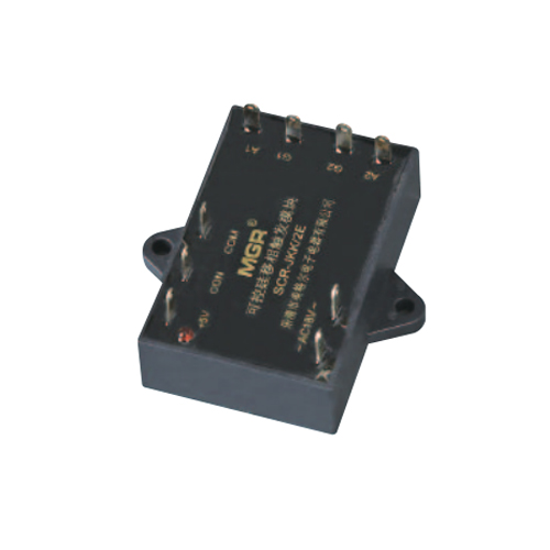
◎ 单相双路可控硅移相触发器模块 (SCR-JKK/2)
SINGLE PHASE DUAL CHANNEL THYRISTOR PHASE-SHIFT TRIGGER MODULE (SCR-JKK/2)
◆ 单相双路可控硅移相触发器模块 (SCR-JKK/2) 的原理是在前述的 SCR-JKK 基础上增加一路负半周的可控硅触发信号 , 以实现单相电路中对两只单相可控硅的正负半周同时移相调节 , 除此以外均同 SCR-JKK。
◆ SCR-JKK/2按控制信号的不同, 分以下规格(型号表):
◆ The principle of the single phase dual channel thyristor phase-shift trigger module (SCR-JKK/2) is: On the basis of SCR-JKK, add one thyristor trigger signal of the negative half period to achieve the simultaneous phase-shift adjustment of the positive and negative half periods of two single phase thyristors in the single phase circuit. Except for it, the parameters and performance of SCR- JKK/2 are the same as SCR-JKK.
◆ According to different control signals, SCR- JKK/2 can be divided into four types: E, F, G, and H types. The following is the specification model table.


◎ 控制电压 U CON 与可控硅输出导通角 α 关系曲线 ( 阻性负载 ) 及波形图
The relationship and waveform of the control voltage U CON and the conduction angle α of the thyristor (when resistive load)

◎ 外形尺寸 Overall dimensions

◎ 注意事项及改进说明
Precautions and improvements
◆ 请 用 户 特 别 注 意 : TRIAC-JKK, SCR-JKK 和SCR-JKK/2 这三类模块为强电触发方式可控硅 ( 而不是通常脉冲变压器触发可控硅的门极和阳极 ), 所以在可控硅门极损坏而不能被触发导通的情况下 , 如触发器模
块仍有控制电压 , 则电网的电流从 A 端进入 , 从 G 端再到负载 , 而电网电压的极大部分则降在 A, G 两端 , 这个电压电流所产生的发热 , 在数秒中内将使 A, G 两端内部器件烧毁 . 这种由于可控硅门极损坏而导致触发器模块损坏的情况 , 是这三个器件最主要的不足。
◆ 改进说明 : ”移相触发器模块系列”中 , 为提高调压系统 ( 由移相触发器模块 , 可控硅及同步变压器组成的 )的静态 dv/dt 指标 , 使系统在合闸上电时不致瞬间导通一下 , 图 B-1/ 图 B-2 以及图 C-1/ 图 C-2 可改进为如下 : 移相触发器模块的 A 极接到对应的 RC 吸收回路的中点 , R,C 的接法必须为图上的位置 ( 即 R 的一端接单相可控硅的阳极或双向可控硅的主电极 T1, C 的一端接单相可控硅的阴极或双向可控硅的主电极 T2), R 和 C的位置不能交换 . 其中 R 选 15Ω~30Ω, 功率大于等于3W; C选0.1μf~0.47μf, 250VAC或400VAC以上。
◆ SPECIAL ATTENTION: TRIAC-JKK, SCR-JKK and SCR-JKK/2 these three types modules adopt strong electric trigger mode, so when the module cannot be triggered to conduction due to the damage of the thyristor gate, if there still remains voltage on the trigger module, the current of the power grid will enter from the A port and then pass through the G port to the load, and the vast majority of the power grid voltage will be applied to both ends of A and G, after that there will be huge heat generated caused by the high voltage and current, which will burn and damage internal components connected to the both ends of A and G in few seconds. It is the main deficiency of these three kinds of module s that the trigger module will be damaged caused by the damage of the gate of the thyristor.
◆ IMPROVEMENT DESCRIPTIONS: For these phase-shift trigger module series, in order to improve the static dv/dt of the voltage regulation system (consisting of the phase-shift trigger module, the thyristor and the synchronous transformer) and also prevent the voltage regulation system from the transient conduction once when the system is switched and powered on, the improvements of Figure B-1/B-2 and Figure C-1/C-2 as follows: The A port of the phase-shift trigger module should be connected to the midpoint of the corresponding RC snubber loop, and the connection method of R and C must be as shown in the figure (that is, one end of R should be connected to the anode of the single- phase thyristor or the main electrode T1 of the TRIAC, and one end of the C should be connected to the cathode of the single phase thyristor or the main electrode T2 of the TRIAC), and the positions of R and C cannot be exchanged. The resistance of the RC circuit is generally 15~30Ω, 3W or more, and the capacitance is 0.1~0.47μf, 250VAC/400VAC or more.point of the corresponding RC absorption circuit, R, C, the location of the connection must be on the drawing (i.e. R pick up at the end of the single phase SCR anode or bidirectional thyristor T1, the main electrode C pick up at the end of the single phase SCR cathode or two-way thyristor main electrode T2), the location of the R, C can't exchange. Which R selected 15 Ω - 30 Ω, power is greater than or equal to 3 w; C choose 0.1uf- 0.47uf,250VAC or 400VAC.